As an Amazon Associate, we earn from qualifying purchases. Some links on this site are affiliate links at no extra cost to you. Our recommendations are based on thorough research and editorial judgment.

Troubleshooting Radar Motion Bulbs in Enclosed Fixtures
1. Compatibility: Technician should verify socket (E26/E27), fixture IP65 rating, mains voltage (120V), and bulb wattage against fixture maximum, replace parts. 2. Enclosure: Use acrylic or polycarbonate under 3 mm thickness, maintain >50 mm clearance from metal brackets, avoid metal >1 mm. 3. Sensor: Radar penetrates thin barriers and detects up to 20 m, test in open fixture 72 hours. 4. Troubleshoot wiring, insulation, and EMI per checklist; continue for detailed procedures and professional guidance.
Key Takeaways
- Verify socket type, wattage, and supply voltage match fixture ratings; avoid LEDs/fluorescents with STL200-compatible radar bulbs.
- Use acrylic or polycarbonate under 3 mm thickness; metal thicker than 1 mm will block radar signals.
- Maintain at least 50 mm clearance from obstructions and preserve a 30° sensor aperture for reliable detection.
- Test bulbs in a compatible open fixture for 72 hours under rated conditions, logging activations and ambient lux.
- Inspect wiring and corrosion, reduce EMI by separating electronics 0.5–1.5 m, and hire a professional if troubleshooting fails.
Assessing Bulb and Fixture Compatibility
1. Inspect socket and enclosure compatibility: Verify that the bulb matches the fixture socket type, for example E26 or E27, and confirm that the enclosed fixture rating allows the radar motion bulb, since heat accumulation in sealed fixtures commonly shortens life, causing malfunction. 2. Check electrical ratings and wattage limits: Confirm bulb wattage does not exceed the fixture’s maximum limit, verify supply voltage and any dimmer compatibility, and observe manufacturer recommendations for STL200 sensor-compatible lamps, avoiding LEDs and fluorescents. 3. Test performance in known-good fixtures: Use a compatible open fixture to run at least 72 hours under rated conditions to detect unresponsiveness or early failure, document results, and replace faulty bulbs before final installation. Maintain records of test parameters, temperature, and electrical measurements periodically. Additionally, ensure your motion sensor light has a weatherproof rating like IP65 or IP66 to withstand outdoor conditions and prolong its lifespan.
Recommended Products

3000K Soft White and Energy Saving: 100-watt replacement uses only 11.5 watts of energy and produces about 1050 lumens of light, saving more than 80% electricity bill compared with equivalent traditional bulbs. Motion sensor light gives off a soft white glow, 3000 Kelvin, often yellow in appearance; best for living rooms, dining rooms, bedrooms, and outdoor spaces.

Motion Sensor Dusk to Dawn - These dusk to dawn light bulbs light up when motion is sensed in the detective area at night or in the dark environment. With the photocell sensor these security light bulbs deactivate during the daylight hours but light up at night when in range. No hands on action needed to control your exterior lights. You will have the convenience and safety knowing your lights will provide bright light when in range.
How Radar Sensors Differ From PIR Sensors

Comparative overview: Radar motion sensors emit electromagnetic waves, commonly at 24 GHz or 60 GHz, and detect Doppler shifts from moving targets, whereas passive infrared (PIR) sensors measure thermal radiation in the 8–14 µm band and require direct line-of-sight to a heat source. 1. Detection principles: Radar Sensor actively transmits, receives phase and frequency changes, and can detect movement through thin barriers, while PIR passively senses infrared flux from warm bodies. 2. Performance metrics: Radar offers higher sensitivity, longer range up to 20 meters in open spaces, and consistent operation across temperatures, PIR ranges are typically 5–10 meters and need unobstructed view. 3. Practical use: For enclosed fixtures choose sensors based on required coverage, false-trigger tolerance, and installation constraints. Many security lights such as USTELLAR 100W and SANSI models incorporate features like IP65 weatherproof ratings, allowing them to function efficiently in various conditions. This guidance aids selection decisively.
How Enclosure Design Affects Radar Detection

Enclosure design directly affects radar motion sensors, because materials, thickness, and aperture geometry change transmission and reflection of microwave energy, altering detection capabilities. Metal housings with thickness greater than 1 mm or mesh spacing below 5 mm can block GHz bands, while acrylic or polycarbonate panels under 3 mm transmit adequately, use 2 mm when possible. Avoid placing sensors within 50 mm of mounting brackets or components that could be obstructed by nearby structures, position sensors with clear line-of-sight through openings at least 30° wide. Consider sensor operating principle and enclosure specs during setup for reliable performance. If inconsistent, test with reference targets at 1–5 meters and adjust aperture size or material accordingly promptly. Stainless steel outdoor lights, known for their rust-resistant properties, offer durability and aesthetic appeal, making them ideal for various garden designs.
Power Supply and Wiring Troubleshooting

Although often overlooked, power supply and wiring integrity determine reliable operation of radar motion bulbs, because steady mains voltage, intact conductors, and secure terminations directly govern sensor activation, filament or LED illumination, and electronic stability. 1. Verify supply: check power with a low impedance meter, confirm ~120V under load, inspect for surges, interruptions, or tripped breakers that can stop operation. 2. Inspect conductors: examine for open neutral conditions, corrosion, damaged insulation, and ascertain socket contacts are tight to prevent intermittent faults. 3. Test connections: tighten terminations, replace burnt connectors, and re-seat bulbs to restore continuity. 4. Sensor interaction: confirm electrical connections do not introduce noise that affects motion sensors, document findings for safe corrective action. Use caution, de-energize circuits, and verify with PPE present. Additionally, ensure that any outdoor lighting fixtures have the appropriate IP rating to withstand environmental conditions, as discussed in the knowledge base, to ensure long-term functionality.
Recommended Products

Perfect for closets, basements, Utility rooms
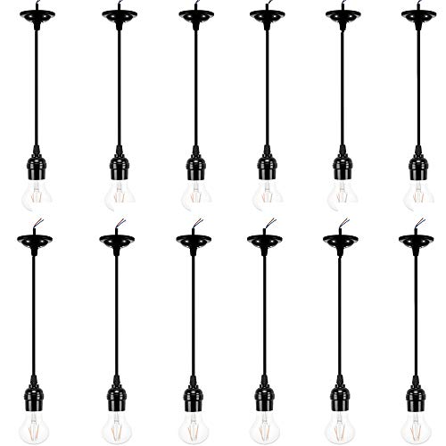
★Standard. ACBungji pendant light kit has an electrical rating of 250VAC and 250W, either wire can be neutral for alternating current, fits for 1inch/2.6cm lamp base cap

#HIGH BRIGHTNESS: Each led under cabinet puck light outputs 200 lumen, total giving out 1200lm, perfectly meets normal lighting needs.
Identifying Environmental and Electromagnetic Interference

- Environmental factors: Radar motion bulbs in enclosed fixtures can register wind-blown objects or wildlife, producing false activations; designers should allow 0.5–1.5 m clearance from vents or foliage, avoid reflective surfaces within 30 cm, and limit sensor aperture obstructions to preserve sensor performance, maintenance is essential to verify placement and seals.
- Electromagnetic interference: Nearby electronics such as microwaves or routers may introduce electromagnetic interference that degrades detection algorithms, maintain at least 1–2 m separation from high-power transmitters, shield wiring with grounded conduit where feasible, and select fixtures with RF-tolerant components to sustain ideal functionality.
- Diagnostic procedure: Log activation timestamps, visualize patterns, and adjust placement incrementally to confirm causation. Record ambient light lux levels, noting readings above 300 lux as potentially disruptive. Adjustable heads or PAR38 compatibility in some security lights can help improve sensor accuracy by allowing for customizable detection angles, minimizing the impact of environmental interference.
Cleaning, Maintenance, and Lens Care
- Regular maintenance: cleaning the sensor, maintain peak performance by wiping the lens and enclosure with a damp, lint-free cloth, using non-abrasive solutions, avoiding solvents, and removing spider webs or debris that cast shadows or scatter radar returns. Inspect covers for scratches exceeding 0.2 mm depth, which can degrade detection.
- Scheduled checks: perform visual inspections every 3 months, document lens condition, and replace damaged covers promptly to preserve sensitivity settings and operational range.
- Troubleshooting notes: common problems with motion detection often stem from soiling, obstructions, or degraded optics; verify clear line of sight and enclosure seals.
- Implementation: log maintenance, measure residue thickness when present, and follow manufacturer torque and sealing specifications for reassembly. Test mode guidance provided separately. Record ambient conditions, humidity and temperature, as these affect radar returns and lens condensation risk periodically.
Step-by-Step Testing Procedures and Test Mode
Several key actions are required for a controlled test procedure. 1. Enter test mode by toggling settings four times until the light turns off, this activates continuous detection for assessment. 2. Testing the sensor: walk across the detection field at 1 to 3 m/s, observe two-second activation and four-second recovery intervals, record responses. 3. Monitor sensitivity level by adjusting according to manufacturer steps, note changes in trigger distance measured in meters, and document thresholds. 4. Eliminate nearby movement to prevent no surrounding motion will interfere with the sensors, suspend HVAC and remove moving objects. 5. Vary environmental conditions such as lighting and obstructions, test each condition for two minutes, then exit or allow automatic revert. Document findings, include timestamps and measured detection distances.
In extreme weather conditions, such as very cold or hot climates, motion sensors may experience reliability issues, which is why it’s crucial to evaluate materials for durability and check the manufacturer’s guidelines on temperature ranges.
Optimal Placement and Mounting Strategies in Enclosed Fixtures
Installer’s placement overview: mount radar motion bulbs with at least 5 cm radial clearance inside fixtures, orienting the sensor toward the intended detection area. 1. Sensor orientation and clearance: The installer should guarantee enough clearance around the lamp, position the radar sensor to face the monitored zone, and verify the sensor is aimed away from internal walls to reduce reflections. 2. Spacing and placement: Maintain 16–20 feet between motion-sensing fixtures to prevent overlapping detection fields, and avoid direct sunlight or bright adjacent sources. 3. Thermal and ventilation considerations: Provide ventilation openings to limit heat buildup that degrades detection stability and bulb longevity within the lighting system. 4. Verification: Test in-situ, adjust aim, and document placement. Guides should record ideal placement for each fixture installed. Additionally, ensure the motion sensor lights comply with local light pollution regulations to avoid any legal issues and maintain environmental harmony.
Recommended Products

【Remote & Wall Switch Dual Control】 Enjoy the convenience of switching modes from up to 9.84 ft away with the remote — or simply use your wall switch. Just click to turn it on/off, or double-click to change modes. No more climbing ladders to adjust settings!

Simple Installation: you only need to screw our motion light socket adapter into the existing bulb socket, and then screw the bulb into the other end of our lamp holder to complete the installation without too many tools and extra wires, convenient for you to install and replace

Automatic Dusk-to-Dawn Outdoor Flood Light - Experience reliable outdoor lighting from sunset to sunrise. This PAR38 LED dusk to dawn flood light bulb outdoor activates automatically, boosting home security and visibility without timers or switches. Ideal for driveways, porches, garages, and entryways.
Signs It’s Time to Replace or Upgrade the Sensor Bulb
When a radar motion bulb fails to activate, triggers falsely, or stays illuminated despite correct mounting and wiring, replacement is indicated pending diagnostics. 1. Functional failure: If the sensor leads draw abnormal power, exceeding fixture ratings (for example 0.5–1.5 W standby), or the unit remains lit indefinitely, replace the device, as circuitry failed. 2. Erratic triggering: Common Issues With Motion include repeated false activations within 1–5 seconds, caused by degraded antennae or environmental reflection, requiring recalibration or replacement. 3. Short lifespan: Bulbs lasting less than 12 months under normal duty cycles require upgrade to higher-spec models with improved sensitivity and smart features. 4. Verification: Use multimeter, documented test strips to assess functionality of motion detection. Replace when diagnostics confirm problems associated with motion. Battery-powered motion lights are ideal for enhancing safety and convenience in various settings, making them a reliable upgrade choice for those experiencing issues with radar motion bulbs. Proceed with caution and documentation.
Recommended Products

【Dual Intelligent Sensor Modes】This solar street light supports two working modes: dim light when no motion is detected and bright when people approach, or off when idle and full brightness when triggered. The radar sensor detects movement up to 6–8m away, saving energy while ensuring security.
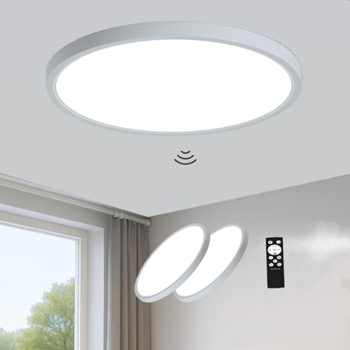
12 Inch Motion Sensor Ceiling Light: Built-in microwave sensor with 360 detection and 5-20 ft range automatically turns on when motion is detected and shuts off after 30s/180s. No more fumbling for switches in the dark, suitable for hallways, stairs, closets, garages, and basements. (Note: This sensor light is hardwired, AC120V, not battery-powered)

【Wired Radar Motion Sensor Ceiling Light】12 inch Hardwired 5.8G Radar Motion Sensing Ceiling Light automatically turns on when motion is detected within 3-20 feet (selectable) and automatically turns off 5S/30S/1MIN/5MIN (4 Timer) later when motion disappears. With a 5.8G 360° microwave motion sensor and a high-quality light sensor, the light is more sensitive to motion and light compared to a conventional infrared sensor. It will not be disturbed by environment, temperature, dust etc.
Hiring a Professional: What to Expect and When to Call
- A professional electrician should be contacted when basic troubleshooting fails, when bulbs continuously activate or do not illuminate, or when the power source shows irregular voltage, for example below 110 VAC or fluctuating more than ±10%.
- Expect the technician to inspect wiring, verify neutral continuity with a meter, test breakers, and measure current draw with a clamp meter, then document findings and recommendations.
- Professionals will adjust sensitivity settings and motion sensor placement, recommend compatible bulbs for enclosed fixtures such as specific LED models with integrated drivers, and provide maintenance guidance to improve long-term reliability.
- Typical service visits last 45–90 minutes, technicians carry reference data sheets, replacement bulbs, calibrated meters, and they will advise on costs, safety precautions, and performance metrics.
- For outdoor security, weather-resistant lights ensure durability and reliability, making them ideal for withstanding harsh conditions like rain or snow.
Recommended Products

✅ NO REPLACEMENT BULBS REQUIRED - The LED array included inside the barn lights are rated to last 50,000 hours (20 years with average use) before needing to be replaced.
✅ NO REPLACEMENT BULBS REQUIRED - The LED array included inside the barn lights are rated to last 50,000 hours (20 years with average use) before needing to be replaced.
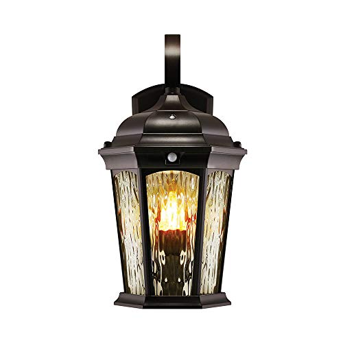
Dusk to Dawn Technology – Keep your home as efficient as possible, with dusk to dawn technology the animated flame bulb will immediately ignite when the sun starts to set – appearing as a traditional gas lamp and turning off as sunrise approaches.
Frequently Asked Questions
What Kind of Light Bulb Can I Use in an Enclosed Fixture?
40% of failures occur from overheating; one should use enclosed-fixture-rated LED bulb types for enclosed fixture compatibility, considering Motion bulb features and enclosed fixture design to avoid heat dissipation issues and guarantee safe, long-lasting operation.
Why Do LED Light Bulbs Not Work in Some Fixtures?
LEDs often fail in some fixtures because LED compatibility issues, Fixture heat buildup, Bulb wattage limits, Sensor placement errors and Enclosure ventilation concerns cause overheating, interference, or inadequate sensing, reducing performance and shortening bulb lifespan.
Why Is My Motion Sensor Light Bulb Not Working?
Like a lighthouse shrouded in fog, the bulb often fails because they recommend motion sensor troubleshooting, checking bulb compatibility issues, power supply problems, adjusting sensor sensitivity settings, and eliminating environmental interference factors for safe operation.
What Is the Most Common Problem With PIR Sensors?
The most common problem with PIR sensors is obstruction causing missed detections; issues often stem from PIR sensor sensitivity, reduced motion detection range, environmental interference, wrong installation height, or poor sensor alignment accuracy and debris.


